
01Explain the responsibilities of all seven layers of the OSI model.
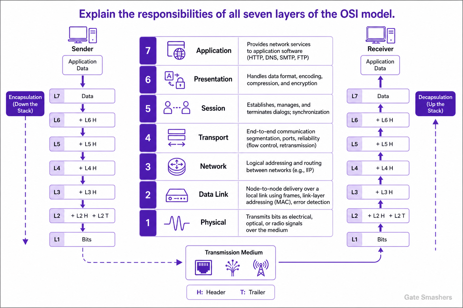
The OSI model is a seven-layer reference model that separates network communication responsibilities. From Layer 7 to Layer 1: Application provides network services to application software; Presentation handles data representation, translation, compression, and encryption; Session establishes, manages, and terminates dialogs; Transport provides end-to-end communication between application processes, including segmentation, multiplexing with port numbers, and, where supported, reliability and flow control; Network provides logical addressing and routing between networks; Data Link provides node-to-node delivery over a local link using frames and link-layer addressing, with error detection; and Physical transmits bits as electrical, optical, or radio signals over the medium. Data is encapsulated as it moves down the sender's stack and decapsulated as it moves up the receiver's stack.
OSI model purpose
The Open Systems Interconnection (OSI) model organizes communication functions into seven conceptual layers. Each layer serves the layer above it and relies on the layer below it, which helps separate concerns for protocol design, interoperability, and troubleshooting.
Upper layers: application-facing functions
Layer 7, Application, provides network services used by application software. Common examples include services for web access, email, file transfer, and name resolution.
Layer 6, Presentation, is responsible for the representation of data so that communicating applications can interpret it consistently. Its functions include translation between data formats or character encodings, compression, and encryption or decryption.
Layer 5, Session, establishes, manages, and terminates dialogs between communicating applications. In the OSI model, it can also coordinate dialog control and synchronization points for longer exchanges.
- Layer 7 — Application: Provides network services to application software; examples often associated with this layer include HTTP, DNS, SMTP, and FTP.
- Layer 6 — Presentation: Handles data format, encoding, compression, and encryption-related representation functions.
- Layer 5 — Session: Manages communication dialogs and synchronization between applications.
Transport and internetwork delivery
Layer 4, Transport, provides communication between application processes on end systems. It can segment and reassemble data, use port numbers to identify application endpoints, and provide reliability, ordered delivery, flow control, and retransmission when the transport protocol supports those functions.
Layer 3, Network, moves packets between networks. It uses logical addressing and routing to select paths toward a destination; IP is a common network-layer protocol.
- Layer 4 — Transport: Provides process-to-process delivery and may provide reliability, ordering, flow control, and error recovery. TCP and UDP are commonly mapped to this layer.
- Layer 3 — Network: Provides logical addressing and routing of packets across interconnected networks. Routers primarily operate at this layer.
Local-link transmission and data flow
Layer 2, Data Link, provides delivery over a single local link or network segment. It organizes data into frames, uses link-layer addressing such as MAC addresses where applicable, and commonly provides error detection. Ethernet switches primarily operate at this layer.
Layer 1, Physical, transmits bits over the medium as electrical, optical, or radio signals. It covers signaling, connectors, cabling or radio media, and other physical transmission characteristics.
On the sender, application data is encapsulated as it moves down the layers; lower-layer control information is added before transmission. On the receiver, the corresponding information is processed and removed as data moves up the stack. Real protocol suites do not always implement the seven OSI layers as separate components, but the model remains useful for describing responsibilities.
- Layer 2 — Data Link: Provides local-link framing, link-layer addressing, and error detection.
- Layer 1 — Physical: Carries bits over the physical medium using electrical, optical, or radio signaling.
02Compare the OSI model with the TCP/IP model.
The OSI model is a seven-layer conceptual reference model, while the TCP/IP model describes the Internet protocol suite and is commonly presented with four layers. TCP/IP combines the OSI session, presentation, and application functions into its application layer, and commonly combines OSI data-link and physical functions into its link or network-access layer. The transport and network/internet functions map closely between the models. OSI is mainly used as a framework for understanding, design, and troubleshooting; TCP/IP is the model reflected in deployed Internet protocols such as TCP, UDP, IP, HTTP, and DNS.
Purpose and structure
The OSI model standardizes networking functions into seven distinct layers: Physical, Data Link, Network, Transport, Session, Presentation, and Application. It is a reference framework that helps describe how networking responsibilities can be separated.
The TCP/IP model is based on the Internet protocol suite and is commonly represented as four layers: Link (or Network Access), Internet, Transport, and Application. Some presentations use five layers by separating physical and data-link functions.
Layer mapping
The models do not map one-to-one at every boundary, but the following mapping is the usual comparison.
- TCP/IP Application: Corresponds broadly to the OSI Application, Presentation, and Session layers.
- TCP/IP Transport: Corresponds closely to the OSI Transport layer.
- TCP/IP Internet: Corresponds closely to the OSI Network layer.
- TCP/IP Link / Network Access: Covers functions broadly corresponding to the OSI Data Link and Physical layers in the four-layer presentation.
Protocols and practical use
The OSI model is not tied to one particular protocol suite; it provides a general way to classify networking functions. The TCP/IP model is closely associated with the protocols used for Internet communication.
For example, HTTP and DNS are application-layer protocols, TCP and UDP are transport-layer protocols, and IP operates at the Internet layer. In practice, engineers often use both models: TCP/IP to describe deployed protocol behavior and OSI terminology to isolate responsibilities during design and troubleshooting.
03Explain encapsulation and de-encapsulation in computer networks.
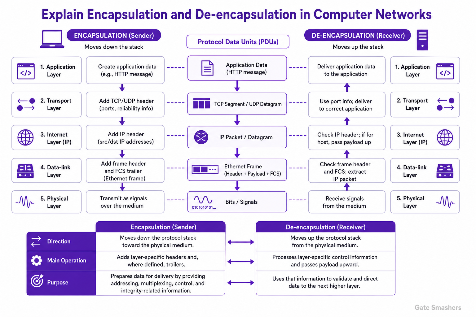
Encapsulation is the process of adding protocol control information to application data as it moves down the protocol stack at the sender. Each layer treats the data from the layer above as its payload and adds its own header, and some protocols also add a trailer. De-encapsulation is the reverse process at the receiver: each layer examines and processes its control information, removes it as appropriate, and passes the remaining payload to the layer above. For example, an HTTP message may be encapsulated in a TCP segment, then an IP packet, then an Ethernet frame, and finally transmitted as signals over the physical medium. At the destination, the Ethernet frame is processed first, followed by the IP packet and TCP segment, until the original application data is delivered to the appropriate application.
Concept
Encapsulation enables layered communication. A protocol layer adds information needed for its own function without requiring higher layers to manage lower-layer details. This information can include addresses, protocol identifiers, sequencing information, and integrity-checking fields.
De-encapsulation uses that information at the receiving system to identify, validate where applicable, and deliver the data to the next higher layer.
Encapsulation at the sender
As data moves downward through a TCP/IP-style stack, it is wrapped by successive protocol layers.
- Application layer: Creates application data, such as an HTTP message.
- Transport layer: TCP or UDP adds a transport header, including port information. TCP segments data and provides reliability-related control information; UDP forms a datagram with a simpler header.
- Internet or network layer: IP adds a header containing source and destination IP addresses, producing an IP packet or datagram.
- Data-link layer: A link protocol such as Ethernet encapsulates the IP packet in a frame. Ethernet adds a header and a frame check sequence trailer.
- Physical layer: Transmits the frame as signals over the selected medium.
De-encapsulation at the receiver
The receiving system processes the data in the opposite direction. The data-link layer accepts the frame and processes link-layer information. The IP layer processes the IP header and, if the packet is for the host, passes its payload upward. The transport layer uses the transport header, including the destination port, to deliver data to the appropriate application or service.
At each stage, a layer generally removes or does not forward the control information intended for that layer. The application ultimately receives the original application-layer data.
Protocol data units
The exact names vary by protocol and teaching model, but a common transmission sequence is: application data, transport segment or datagram, IP packet or datagram, data-link frame, and physical-layer bits or signals. The receiver processes these units in the reverse order.
04Differentiate between a hub, switch and router based on how they forward data.
A hub repeats an incoming signal to all other ports without examining addresses. A switch forwards Ethernet frames based on the destination MAC address, sending known unicast traffic only to the associated port and flooding unknown-unicast traffic within the VLAN. A router forwards IP packets between networks by looking up the destination IP address in its routing table and sending the packet to the selected next hop or outgoing interface.
Hub forwarding
A hub operates at the physical layer. When it receives a signal on one port, it repeats that signal out all other ports. It makes no MAC-address or IP-address forwarding decision, so every connected device receives the transmission signal.
- Data handled: Bits or electrical/physical signals.
- Forwarding basis: No address-based decision; the signal is repeated to other ports.
Switch forwarding
A Layer 2 switch forwards Ethernet frames within a LAN or VLAN. It learns source MAC addresses and associates them with ingress ports. For a known unicast destination MAC address, it sends the frame only through the corresponding port rather than all ports.
If the destination MAC address is not in the switch's forwarding table, the switch floods the frame through relevant ports in the same VLAN, except the port on which it arrived. Broadcast traffic is also forwarded within the VLAN.
- Data handled: Ethernet frames.
- Forwarding basis: Destination MAC address and the switch's MAC address table, scoped to a VLAN.
Router forwarding
A router operates at the network layer and connects different IP networks. It examines the destination IP address, consults its routing table, and forwards the packet through the selected outgoing interface or to a next-hop router.
Unlike a switch, a router does not use the destination MAC address to select the end-to-end route. MAC addresses are used only for local-link delivery on each side of the router.
- Data handled: IP packets.
- Forwarding basis: Destination IP address and the routing table.
Traffic scope and broadcast domains
A hub and a switch do not route traffic between IP networks. A hub repeats traffic across its connected ports, while a switch limits known unicast traffic to the required port. A switch creates separate broadcast domains when ports are placed in different VLANs.
Routers separate broadcast domains and route packets between IP networks. Traffic intended for another IP network is sent to a router, which determines where to forward it next.
05Why does a device need both a MAC address and an IP address for communication?
IP and MAC addresses serve different scopes. An IP address identifies the source and intended destination for routing between networks, while a MAC address is used to deliver a frame over the current local Ethernet or Wi‑Fi link. To send an IP packet, the sender encapsulates it in a Layer 2 frame addressed to either the destination host on the local network or to the next-hop router. At each routed hop, the router forwards the IP packet in a new Layer 2 frame with local source and destination MAC addresses.
Different layers and purposes
IP addressing operates at the network layer. It provides logical addressing that lets routers determine how to forward packets toward the destination network and host.
MAC addressing operates at the data-link layer on technologies such as Ethernet and Wi‑Fi. A MAC address identifies the local interface that should receive a frame on that link. It is not necessarily a permanent physical identifier; it is a link-layer address used for local delivery.
- IP address: Used for routing packets across networks toward an intended destination.
- MAC address: Used to deliver a frame to the next receiver on the current local link.
Sending to a local or remote destination
Before sending on an Ethernet or Wi‑Fi network, a host determines whether the destination IP address is directly reachable on its local network. It then obtains the relevant local link-layer address, commonly through ARP for IPv4 or Neighbor Discovery for IPv6.
If the destination is local, the frame is addressed to the destination host's MAC address. If the destination is remote, the frame is addressed to the default gateway's MAC address, while the IP packet still names the remote destination.
- Local destination: The frame's destination MAC address is the destination host's MAC address.
- Remote destination: The frame's destination MAC address is the next-hop router's MAC address.
What changes at routers
A router receives a Layer 2 frame, removes its link-layer encapsulation, examines the IP packet, and chooses the next hop using the destination IP address. It then sends the packet on its outgoing link inside a newly created Layer 2 frame.
Therefore, the Layer 2 source and destination MAC addresses are local to each routed link and generally change at routers. The original IP source and destination usually remain end-to-end, although mechanisms such as network address translation can modify IP addresses.
Why both are needed
IP addresses answer where the packet is ultimately intended to go across interconnected networks. MAC addresses answer which local interface should receive the frame for the next step. IP routing alone does not provide local frame delivery, and a MAC address alone does not provide routing across separate IP networks.
06How does a switch learn and use MAC addresses to forward frames?
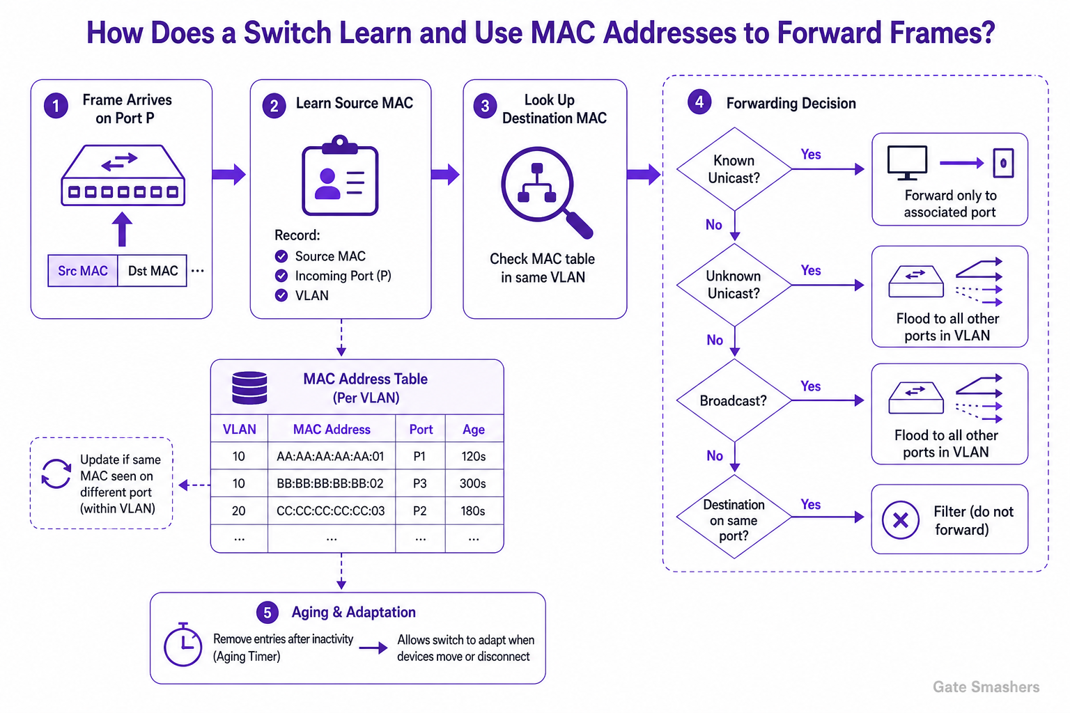
A switch learns MAC addresses by examining the source MAC address of each received Ethernet frame and recording the source MAC, incoming port, and VLAN in its MAC address table. When forwarding the frame, it looks up the destination MAC address in the table. A known unicast frame is sent only to the associated port; an unknown unicast frame is flooded to other ports in the same VLAN; and a broadcast frame is flooded within the VLAN. Entries age out after inactivity, allowing the switch to adapt when devices move.
MAC address learning
When a frame arrives, the switch reads its source MAC address and associates that address with the port on which the frame was received. The association is maintained in the switch's MAC address table, also called a forwarding table or CAM table.
MAC learning is VLAN-specific: the same MAC address is associated with a port within a particular VLAN. If the switch later receives a frame with the same source MAC on a different port, it updates the table to reflect the new location.
Forwarding decisions
After learning from the source address, the switch examines the destination MAC address and consults its MAC address table to determine where to send the frame.
- Known unicast: If the destination MAC is known in the same VLAN, the switch forwards the frame only through the port mapped to that MAC address.
- Unknown unicast: If no table entry exists for the destination MAC, the switch floods the frame out eligible ports in the same VLAN, except the port on which it arrived.
- Broadcast: A frame addressed to the Ethernet broadcast address is flooded out eligible ports in the same VLAN, except the incoming port.
- Same-port destination: If the destination MAC maps to the same port on which the frame arrived, the switch filters the frame rather than sending it back out that port.
Table aging and adaptation
Dynamically learned MAC address entries are normally removed after an inactivity period. Aging prevents stale entries from remaining indefinitely and helps the switch adapt when a device is disconnected or moved to another port.
This learning, forwarding, flooding, and aging process lets a switch build its forwarding information automatically without requiring a manually configured entry for every attached device.
07How does ARP resolve an IP address into a MAC address?
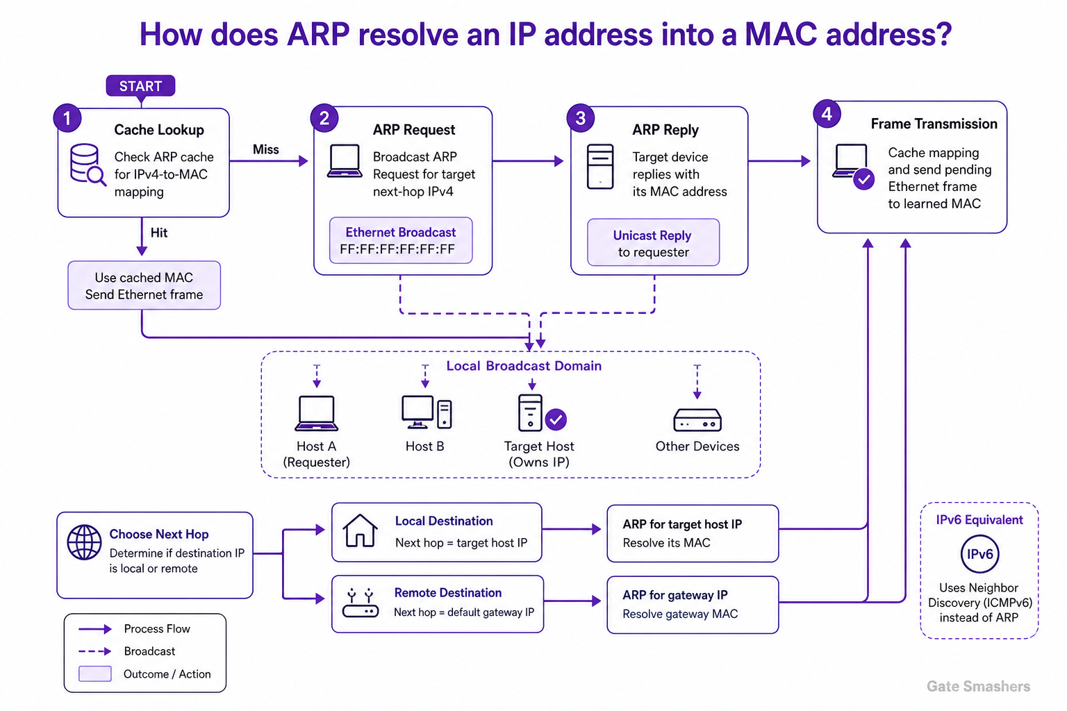
ARP resolves an IPv4 next-hop address to a MAC address on the local network. A host first checks its ARP cache. If no valid mapping exists, it broadcasts an ARP Request asking which device has the target IPv4 address. The device that owns that address normally sends an ARP Reply with its MAC address. The sender caches the mapping and uses that MAC address as the destination address in the Ethernet frame. For an off-link IP destination, the host ARPs for the default gateway's IPv4 address, not for the remote host.
Purpose of ARP
ARP, the Address Resolution Protocol, maps an IPv4 address to a link-layer address such as an Ethernet MAC address. It is used to deliver an Ethernet frame to the appropriate local next hop.
Before using ARP, the sender determines whether the IP destination is on the local network. For a local destination, the next hop is the destination host. For a remote destination, the next hop is usually the default gateway.
ARP resolution process
When a host needs the MAC address for a local next-hop IPv4 address, it first looks for a valid entry in its ARP cache. If an entry is available, it can send the Ethernet frame without issuing a new request.
If no valid entry exists, the host sends an ARP Request in an Ethernet broadcast frame. All devices in the local broadcast domain can receive the request, but the device owning the requested IPv4 address normally responds.
The responding device sends an ARP Reply containing its MAC address, typically directly to the requester. The requester records the IPv4-to-MAC mapping in its ARP cache and sends the pending Ethernet frame using the learned destination MAC address.
- 1. Cache lookup: Check for an existing IPv4-to-MAC mapping.
- 2. ARP Request: Broadcast a request for the target local next-hop IPv4 address.
- 3. ARP Reply: The target device returns its MAC address.
- 4. Frame transmission: Cache the mapping and use the MAC address in the Ethernet frame.
Local-link scope
ARP requests are limited to the local broadcast domain because routers do not forward ordinary Layer 2 broadcasts between routed networks. Therefore, ARP does not obtain the MAC address of a host on a remote network.
For remote traffic, the IP packet still carries the remote destination IP address, but the Ethernet frame is addressed to the MAC address of the local router or other configured next hop.
IPv6 equivalent
IPv6 does not use ARP. It uses Neighbor Discovery, based on ICMPv6, for address resolution and related local-link functions.
08What is a Single Point of Failure (SPOF) in a network?
A Single Point of Failure (SPOF) is a component, link, service, or dependency whose failure makes a network service or critical part of the network unavailable because no redundant component or alternate path can take over.
Definition
A SPOF exists when one failure can interrupt a required function. It may be a physical device, a network connection, a power source, or a supporting service that the network depends on.
Common network examples
The impact of a SPOF depends on what relies on it. A component is a SPOF only when its failure has no effective alternative.
- Router or firewall: A single edge router or firewall can disconnect an organization from external networks if all traffic must pass through it.
- Core switch: Failure of one core switch can isolate downstream networks when there is no alternate switching path.
- Internet uplink: A single WAN or Internet link can prevent external connectivity if that link fails.
- DNS service: A sole DNS server can prevent clients from resolving service names if it becomes unavailable.
- Power dependency: A device with only one power supply or one power source may become unavailable when that source fails.
Reducing SPOFs
SPOFs are reduced by designing redundancy and failover at the appropriate layer. Redundant components must not share an unprotected dependency; for example, two network devices connected to the same power source or single upstream link may still leave a SPOF.
- Device redundancy: Use redundant routers, switches, firewalls, or load balancers where their availability is critical.
- Path redundancy: Provide alternate network links and routing paths.
- Service redundancy: Run critical services on multiple independent instances or locations.
Operational reliability
Redundancy is useful only if failover works when a failure occurs. Health detection, correct configuration, and regular failover testing help ensure that the remaining component or path can assume the workload.
09Compare IPv4 and IPv6.
IPv4 and IPv6 are Internet-layer protocols that provide addressing and routing for IP packets. IPv4 uses 32-bit addresses, while IPv6 uses 128-bit addresses, providing a far larger address space. IPv6 also simplifies the base header, replaces ARP with ICMPv6 Neighbor Discovery, eliminates broadcast, and changes fragmentation behavior. They are not directly interoperable, so dual-stack deployment is commonly used during transition.
Addressing and representation
IPv4 addresses are 32 bits long and are usually written in dotted-decimal notation, such as 192.168.1.10. Its address space contains about 4.3 billion possible addresses.
IPv6 addresses are 128 bits long and are written as hexadecimal groups separated by colons, such as 2001:db8::10. The much larger address space reduces the need to conserve addresses through NAT.
Packet header and fragmentation
An IPv4 header has a variable length of 20 to 60 bytes because options are included in the header. IPv6 has a fixed 40-byte base header; optional functionality is carried in extension headers.
IPv4 routers may fragment packets when required by a link's maximum transmission unit. IPv6 routers do not fragment packets; instead, the sending host uses path MTU discovery and may fragment packets using an IPv6 Fragment extension header when necessary.
Address resolution and traffic delivery
IPv4 typically uses ARP to map a local IPv4 address to a link-layer address. IPv6 uses Neighbor Discovery, which operates through ICMPv6, for address resolution and related local-link functions.
IPv4 supports broadcast traffic. IPv6 has no broadcast; multicast is used where group delivery is needed. IPv6 also supports anycast addressing, in which packets are delivered to one member of an anycast group.
Configuration, NAT, and transition
IPv4 hosts are commonly configured manually or through DHCP. IPv6 supports Stateless Address Autoconfiguration (SLAAC) and DHCPv6; the choice depends on the network's addressing and configuration requirements.
NAT is widespread in IPv4 networks because public IPv4 addresses are limited. IPv6 does not normally require NAT for address conservation, although firewalls are still used for traffic control. Because IPv4 and IPv6 are separate protocols, many networks operate both in dual-stack mode during migration.
10How does NAT allow multiple private devices to access the Internet through one public IP address?
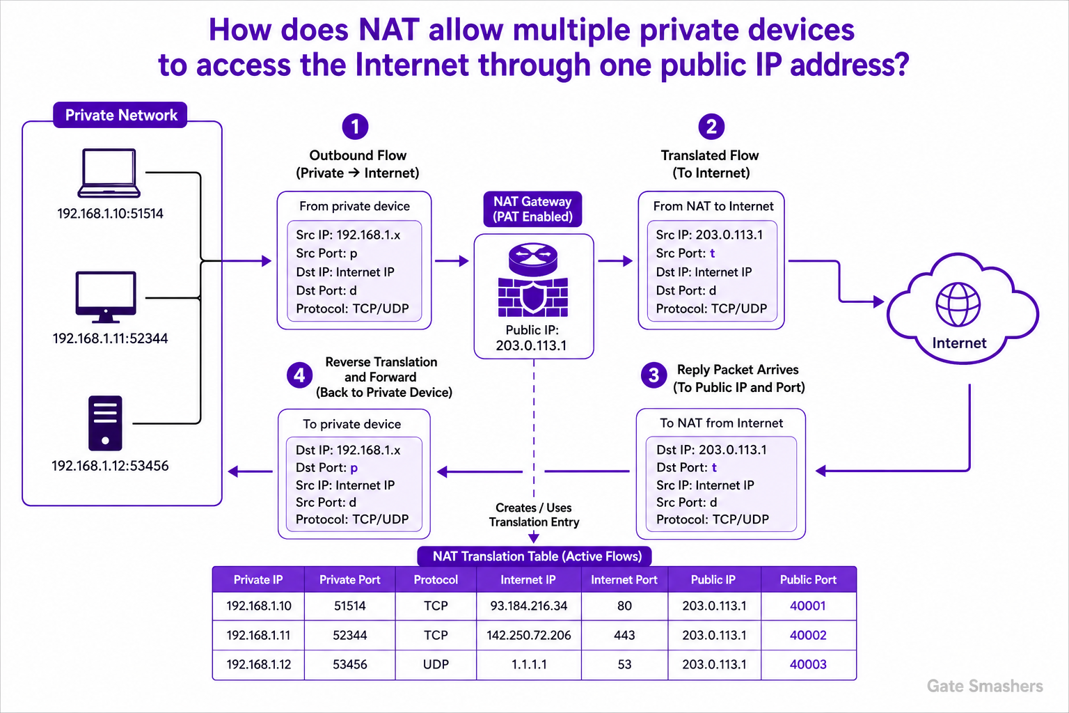
NAT allows private devices to reach the Internet through one public IPv4 address by using Port Address Translation (PAT), also called NAPT or NAT overload. For each outbound flow, the NAT gateway replaces the private source IP address and port with its public IP address and a translated port, then records the mapping. Reply packets sent to that public IP and translated port are matched against the table, rewritten with the original private destination IP and port, and delivered to the correct internal device.
NAT and private addressing
Private IP addresses are not globally routable on the public Internet. A NAT gateway at the network edge translates addresses in packets crossing between a private network and the Internet.
How PAT shares one public address
Basic NAT can use multiple public addresses, but PAT is the mechanism commonly used to let many devices share one public IPv4 address. It distinguishes simultaneous communications by using transport-layer port numbers, along with the relevant protocol and address information.
When an internal device sends traffic outward, the gateway replaces the packet's private source address with its public address. It assigns or selects an external source port so that the flow can be uniquely tracked.
- Internal flow: A private host sends a packet with its private source IP address and source port.
- Translated flow: The NAT gateway sends it to the Internet with the gateway's public IP address and a tracked external port.
Translation table and return traffic
The NAT gateway maintains a translation table for active flows. The entry associates the internal endpoint with the public address and translated port used externally.
When a reply arrives at the public IP address and translated port, the gateway finds the matching entry, changes the destination back to the internal IP address and port, updates packet checksums as required, and forwards the packet to the intended device. This keeps traffic for different private devices and connections separate.
What NAT does and does not provide
PAT conserves public IPv4 addresses and prevents private addressing details from being directly visible in outbound packets. NAT is not, by itself, a replacement for a firewall: firewalling requires explicit traffic-control policy and may include additional inspection capabilities.
11For the classless IP address 192.168.10.70/26, calculate: Network address, Broadcast address, Number of usable host addresses.
For 192.168.10.70/26: Network address: 192.168.10.64 Broadcast address: 192.168.10.127 Number of usable host addresses: 62 Usable host range: 192.168.10.65 to 192.168.10.126.
Prefix and subnet mask
A /26 prefix uses 26 bits for the network portion and leaves 6 bits for host addresses. Its subnet mask is 255.255.255.192.
- Total addresses per subnet: 2^6 = 64
Subnet range
The block size in the last octet is 256
192 = 64. Therefore, the /26 subnets in this octet span 0–63, 64–127, 128–191, and 192–255.
Since 192.168.10.70 falls within the 64–127 range, it belongs to the 192.168.10.64/26 subnet.
Network and broadcast addresses
The first address in the subnet is the network address, and the last address is the broadcast address.
- Network address: 192.168.10.64
- Broadcast address: 192.168.10.127
Usable hosts
In a conventional IPv4 subnet, the network and broadcast addresses are not assigned to hosts. Therefore, the number of usable host addresses is 64 - 2 = 62.
- Usable host range: 192.168.10.65 through 192.168.10.126
- Usable host count: 62
12Explain the DHCP DORA process.
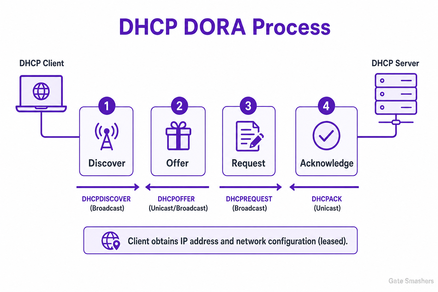
DHCP DORA is the common four-message IPv4 process a client uses to obtain an IP address and related network configuration automatically: Discover, Offer, Request, and Acknowledge.
Purpose
DHCP provides a client with network settings such as an IPv4 address, subnet mask, default gateway, DNS server information, and a lease duration. DORA describes the initial address-allocation exchange between a DHCP client and server.
1. Discover
A client that does not yet know the DHCP server sends a DHCPDISCOVER message to locate available servers. This message is typically broadcast on the local network because the client may not yet have a usable IP address or know the server address.
2. Offer
Each DHCP server able to serve the client may respond with a DHCPOFFER. The offer proposes an IP address and can include configuration options and the lease time for that address.
3. Request
The client sends a DHCPREQUEST to select one offer. During the initial exchange, this request is commonly broadcast, allowing the selected server to identify itself and other servers to withdraw any addresses they offered.
4. Acknowledge and lease
The selected server sends a DHCPACK to confirm the lease and configuration. The client then configures the assigned address and can use the network. The address is leased for a limited period, and the client normally attempts renewal before the lease expires.
DHCP for IPv4 uses UDP: servers listen on port 67 and clients use port 68.
13How does a host decide whether to send a packet directly or through the default gateway?
A host consults its routing table for the destination IP address. It selects the most specific matching route. If the selected route is on-link (directly connected), it sends the packet directly to the destination host after resolving that host’s link-layer address. If the selected route specifies a next-hop router, the host sends the local-link frame to that router’s link-layer address; the IP destination remains the final destination. The default gateway is simply the next hop of the default route, used when no more-specific route matches.
Route lookup determines the path
The host does not decide solely by comparing its address with the destination address. It performs a routing-table lookup for the destination IP address. In the usual routing model, the route with the longest matching prefix is selected; route preference or metrics can break ties between equally specific routes.
The selected route indicates whether the destination is reachable directly on a local link or whether a router must be used as the next hop. A host can have multiple interfaces and multiple directly connected networks, so this decision is made for the selected route and outgoing interface.
When the destination is directly reachable
If the selected route is an on-link route, the host sends the packet directly on that interface. It resolves the destination host’s link-layer address and places that address in the frame destination field.
For example, IPv4 commonly uses ARP for link-layer address resolution, while IPv6 uses Neighbor Discovery. The IP packet still has the destination host’s IP address.
When a router is required
If the selected route names a next-hop router, the host resolves the router’s link-layer address and sends the frame to that router on the local link. It does not try to resolve the link-layer address of the remote destination host.
The router then forwards the packet toward its IP destination. On the first link, the frame destination is the router, but the IP destination remains the final remote host.
Role of the default gateway
A default gateway is the next-hop router configured for the default route, commonly represented by a route with prefix length zero. That route is used only when the routing table has no more-specific matching route for the destination.
Thus, traffic to another network does not always use the default gateway: a more-specific route may select a different router or another directly reachable interface.
14How does traceroute discover the path followed by a packet?
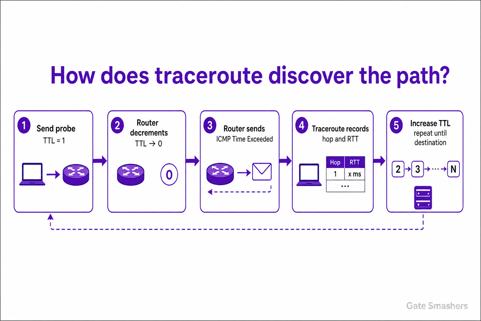
Traceroute discovers a path by sending probe packets with successively larger IPv4 TTL values, or IPv6 Hop Limits. Each router decrements this value when forwarding a packet. When a probe expires at a router, that router normally discards it and returns an ICMP Time Exceeded message. Traceroute uses the reply’s source address and timing to identify that hop and measure an approximate round-trip time. It increases the TTL/Hop Limit one hop at a time until the destination responds or the configured maximum hop count is reached.
TTL and Hop Limit mechanism
IPv4 TTL and IPv6 Hop Limit prevent packets from circulating indefinitely. A router reduces the value as it forwards a packet. If the value expires at that router, the router discards the packet and normally sends an ICMP Time Exceeded response to the source.
Traceroute deliberately uses this behavior to make probes expire at progressively more distant routers.
How hops are discovered
Traceroute first sends a probe with TTL or Hop Limit set to 1. The first router causes the probe to expire and, if it sends an ICMP Time Exceeded response, appears as the first hop.
It then sends probes with values of 2, 3, and higher. A value of 2 allows the first router to forward the probe, while the second router normally returns the Time Exceeded message. Repeating this process reveals responding routers along the forward path.
- Hop address: The source address of the ICMP reply is displayed as the responding hop.
- Delay: The elapsed time between sending a probe and receiving its reply is reported as an approximate round-trip time.
Reaching the destination and probe types
The destination is considered reached when it returns a response appropriate to the probe type. Traditional UDP-based traceroute commonly elicits an ICMP Port Unreachable response from the destination, while ICMP Echo probes can elicit an Echo Reply. TCP-based probes may receive a TCP response from the destination.
Probe formats vary by traceroute implementation and configuration. Common choices are UDP, ICMP Echo Request, and TCP probes; this choice can affect how networks and firewalls handle the probes.
Missing replies and limitations
A timeout, often displayed as an asterisk, means that no expected response was received before the timeout. It does not prove that the router or path has failed: a router may rate-limit or suppress ICMP Time Exceeded messages, or a firewall may filter the probe or reply.
Traceroute shows routers that respond to its probes, not necessarily every forwarding device. Also, the reverse path taken by ICMP replies may differ from the forward path followed by the probes.
15What happens when an IP packet is larger than the network MTU?
If an IP packet is larger than the MTU of the next link, it cannot be forwarded unchanged. In IPv4, it may be fragmented if fragmentation is allowed; if the Don't Fragment (DF) flag is set, the router drops it and typically sends an ICMP message to the source. In IPv6, routers never fragment transit packets: they drop an oversized packet and send an ICMPv6 Packet Too Big message. The sender should then reduce packet size, commonly using Path MTU Discovery and, for TCP, an appropriate MSS.
MTU and oversized packets
The Maximum Transmission Unit (MTU) is the largest IP packet a particular link can carry without fragmentation. Because links along a path can have different MTUs, a packet that fits one link may be too large for a later link.
When a router receives a packet larger than the MTU of its outgoing link, it must fragment it when permitted or discard it and notify the source when possible.
IPv4 behavior
In IPv4, a source or router may fragment an oversized packet into smaller IP fragments when the Don't Fragment (DF) flag is not set. Each fragment is forwarded independently, and the destination host reassembles the original packet.
If DF is set, a router must not fragment the packet. It drops the packet and typically returns an ICMP Destination Unreachable message with the fragmentation-needed indication, allowing the sender to reduce its packet size.
- Cost of fragmentation: Fragments add header overhead, and loss of any fragment prevents successful reassembly of the original packet.
IPv6 behavior
IPv6 routers do not fragment transit packets. If a packet exceeds the outgoing-link MTU, the router discards it and sends an ICMPv6 Packet Too Big message to the source.
The source must send smaller packets. IPv6 allows fragmentation only by the source, using an IPv6 Fragment extension header; the destination performs any required reassembly.
Path MTU Discovery and TCP
Path MTU Discovery (PMTUD) helps a sender determine the largest packet size that can traverse the complete path without fragmentation, using information such as ICMP or ICMPv6 too-big messages.
TCP normally selects a Maximum Segment Size (MSS) intended to keep TCP segments within the expected IP path MTU, reducing the need for fragmentation.
16Compare TCP and UDP.
TCP is a connection-oriented transport protocol that provides reliable, in-order delivery of a byte stream, along with flow control and congestion control. UDP is a connectionless transport protocol that sends independent datagrams and does not provide built-in delivery, ordering, retransmission, flow-control, or congestion-control mechanisms. TCP is suited to applications that need dependable ordered data; UDP is suited to applications that can tolerate loss or implement any needed reliability themselves.
TCP
TCP establishes a connection before transferring application data. It presents data to applications as a continuous byte stream rather than as separate messages.
TCP uses acknowledgements and retransmission to recover from detected loss, delivers received bytes to the application in order, applies flow control so a sender does not overwhelm a receiver, and uses congestion control to adapt its sending behavior to network congestion.
UDP
UDP does not establish a transport connection and preserves application data as individual datagrams. Each datagram is handled independently.
UDP does not inherently guarantee that a datagram will arrive, arrive only once, or arrive in order. It has no built-in retransmission, flow control, or congestion control. An application or a protocol built above UDP must provide any of these features if required.
Overhead and error detection
UDP has a fixed 8-byte header. TCP has a larger, variable-length header, with a minimum size of 20 bytes. TCP’s additional mechanisms generally add protocol overhead and can introduce delay when it waits for missing data to preserve ordered delivery.
Both TCP and UDP use checksums for error detection. UDP checksum requirements differ by IP version: it is optional in IPv4 and required in IPv6.
Choosing between them
TCP is appropriate when complete, ordered data is important, such as for file transfer, remote login, email transport, and many web applications. UDP is appropriate when independent messages and timely delivery are more important than automatic recovery from loss, such as in some DNS exchanges, voice/video traffic, and online gaming.
UDP does not automatically make an application lower latency; its benefit is that it avoids TCP’s connection setup and built-in retransmission and in-order delivery behavior. Actual latency depends on the network and application design.
17Why does TCP use a three-way handshake to establish a connection?
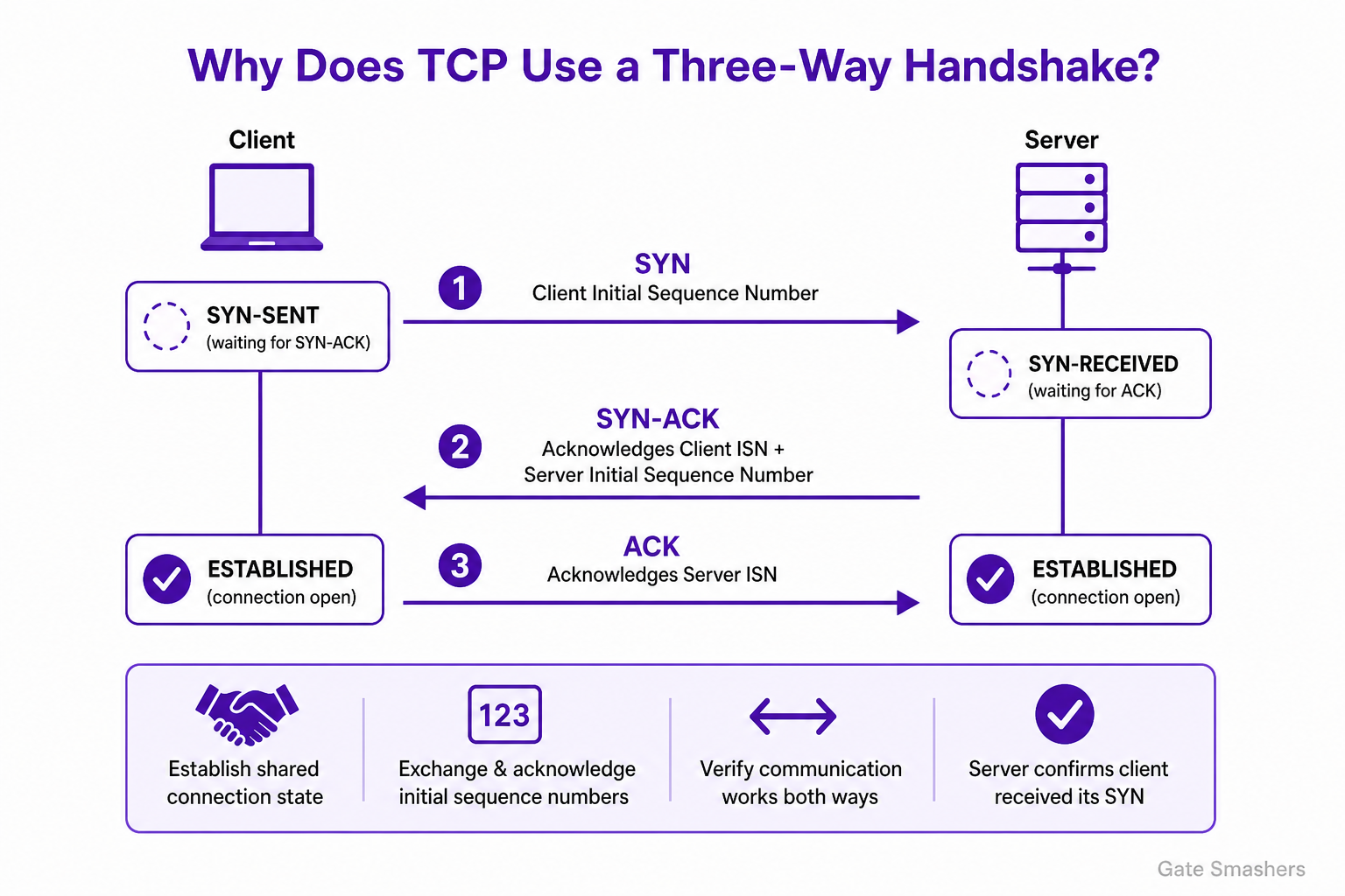
TCP uses a three-way handshake so that both endpoints establish a shared connection state, exchange and acknowledge each other’s initial sequence numbers, and verify that communication can proceed in both directions. The final ACK is necessary because the server must know that the client received the server’s SYN and initial sequence number before treating the connection as established.
What TCP must establish
TCP is a stateful, full-duplex byte-stream protocol. Before data transfer, each endpoint needs to create connection state and learn the peer’s initial sequence number so that bytes can be numbered, acknowledged, and reliably delivered.
The endpoints do not use the same initial sequence number. Each side chooses its own initial sequence number, and the handshake lets the other side acknowledge it.
Three handshake messages
The handshake supplies the required exchange and acknowledgments in three segments.
- SYN: The active opener sends a SYN containing its initial sequence number.
- SYN-ACK: The passive opener acknowledges the client’s SYN and sends a SYN containing its own initial sequence number.
- ACK: The active opener acknowledges the server’s SYN, confirming that it received the server’s sequence information.
Why two messages are insufficient
After sending a SYN-ACK, the server knows that the client initiated a connection and that the client’s initial sequence number was received. However, it does not yet know whether the client received the server’s SYN and initial sequence number.
The third message provides that confirmation. It allows the server to enter the established state only after the client has acknowledged the server’s SYN, avoiding premature allocation of a fully established connection for a request that may not have reached the client.
Protection against stale connection requests
The handshake also helps TCP distinguish a current connection attempt from delayed or duplicate segments from an earlier attempt. A stale SYN alone cannot complete a new connection, because the peer’s SYN must be acknowledged by the original initiator before the server regards the connection as established.
18How does TCP provide reliable and ordered data delivery?
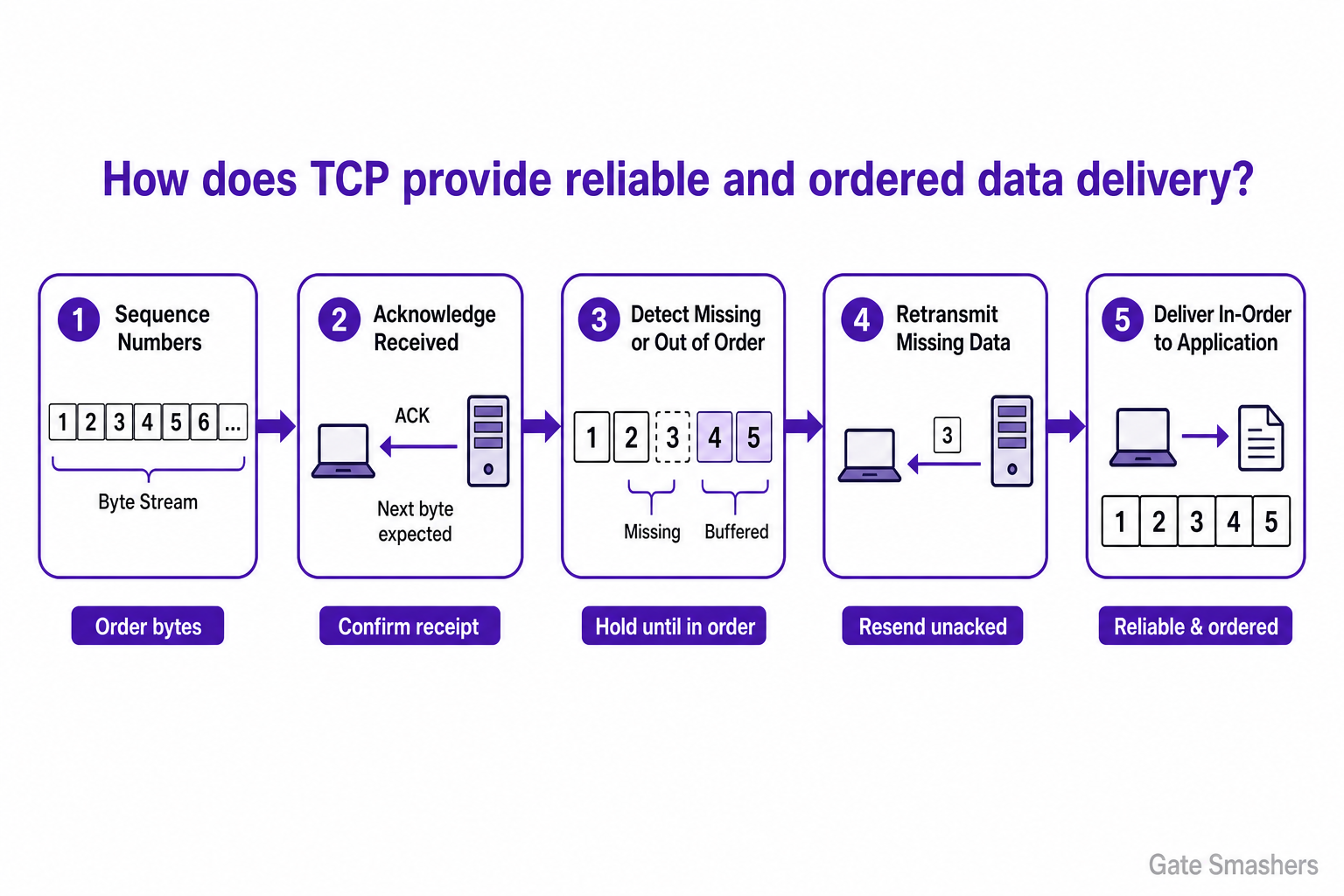
TCP provides reliable, ordered delivery by treating data as a byte stream with sequence numbers. The receiver acknowledges received bytes, detects gaps or corrupted segments, and the sender retransmits data that is not acknowledged. If data arrives out of order, the receiver holds it until missing earlier bytes arrive, then delivers only the contiguous byte stream to the application.
Sequence numbers and ordered byte streams
TCP assigns sequence numbers to bytes in the stream. These numbers let the receiver determine the position of each received byte, identify missing ranges, and recognize duplicate data.
The receiving TCP implementation delivers data to the application only in sequence order. Data that arrives beyond a gap may be buffered until the missing bytes are received.
Acknowledgments and retransmission
The receiver sends acknowledgments indicating the next byte it expects, which cumulatively confirms receipt of all preceding bytes. When supported by both endpoints, Selective Acknowledgment (SACK) can additionally report received noncontiguous ranges.
TCP does not receive an explicit loss notification from IP. Instead, the sender infers loss when an acknowledgment is not received before a retransmission timeout or from patterns of duplicate acknowledgments, then retransmits the missing or unacknowledged data.
Corruption and duplicate handling
Each TCP segment includes a checksum. A segment that fails checksum validation is discarded and is not delivered to the application; the absence of an acknowledgment can cause the sender to retransmit it.
Sequence numbers also allow the receiver to recognize retransmitted or duplicated data and avoid delivering the same bytes more than once to the application.
Flow and congestion control
Flow control uses the receiver-advertised window to limit the amount of unacknowledged data the sender may have in flight, helping prevent the receiver's buffer from being overrun.
Congestion control adjusts the sender's transmission behavior in response to perceived network congestion. It supports efficient network use, but the core reliability mechanisms are acknowledgments, checksums, sequencing, buffering, and retransmission.
19How do ports and sockets allow multiple applications to use the same IP address?
An IP address identifies the destination host or network interface, but it does not identify the receiving application. Transport-layer ports let the operating system deliver incoming TCP or UDP data to the appropriate application endpoint on that IP address. A socket is the operating-system-managed communication endpoint an application uses to send or receive that data. Thus, multiple applications can share one IP address by using different protocol-and-port combinations, and multiple connections to one service can coexist because their connection identifiers differ.
IP address, port, and protocol
The IP address routes a packet to the correct host or interface. After the packet reaches that host, the transport protocol and destination port identify the local service that should receive it. For example, TCP port 443 and UDP port 443 are distinct endpoints because TCP and UDP are different transport protocols.
How applications share one IP address
A host can run several network services on the same IP address when they listen on different ports. The operating system examines the packet's protocol and destination port, then demultiplexes the packet to the socket associated with that local endpoint.
In general, two applications cannot both exclusively bind the same local IP address, transport protocol, and port at the same time. Operating systems may provide controlled sharing mechanisms, but their behavior is implementation-specific.
- Web service: May listen on TCP port 443.
- Remote-access service: May listen on TCP port 22.
- DNS service: May use port 53 with UDP, TCP, or both.
Multiple simultaneous connections
For TCP, a connection is normally identified by the transport protocol, source IP address, source port, destination IP address, and destination port. This five-tuple lets a server accept many simultaneous connections to the same local IP address and port. Each accepted connection has separate communication state even though all clients reach the same listening service.
A socket is commonly described as the operating-system abstraction representing a communication endpoint. A server has a listening TCP socket, while each accepted TCP connection is represented by a separate connected socket.
20How does DNS resolve a domain name into an IP address?
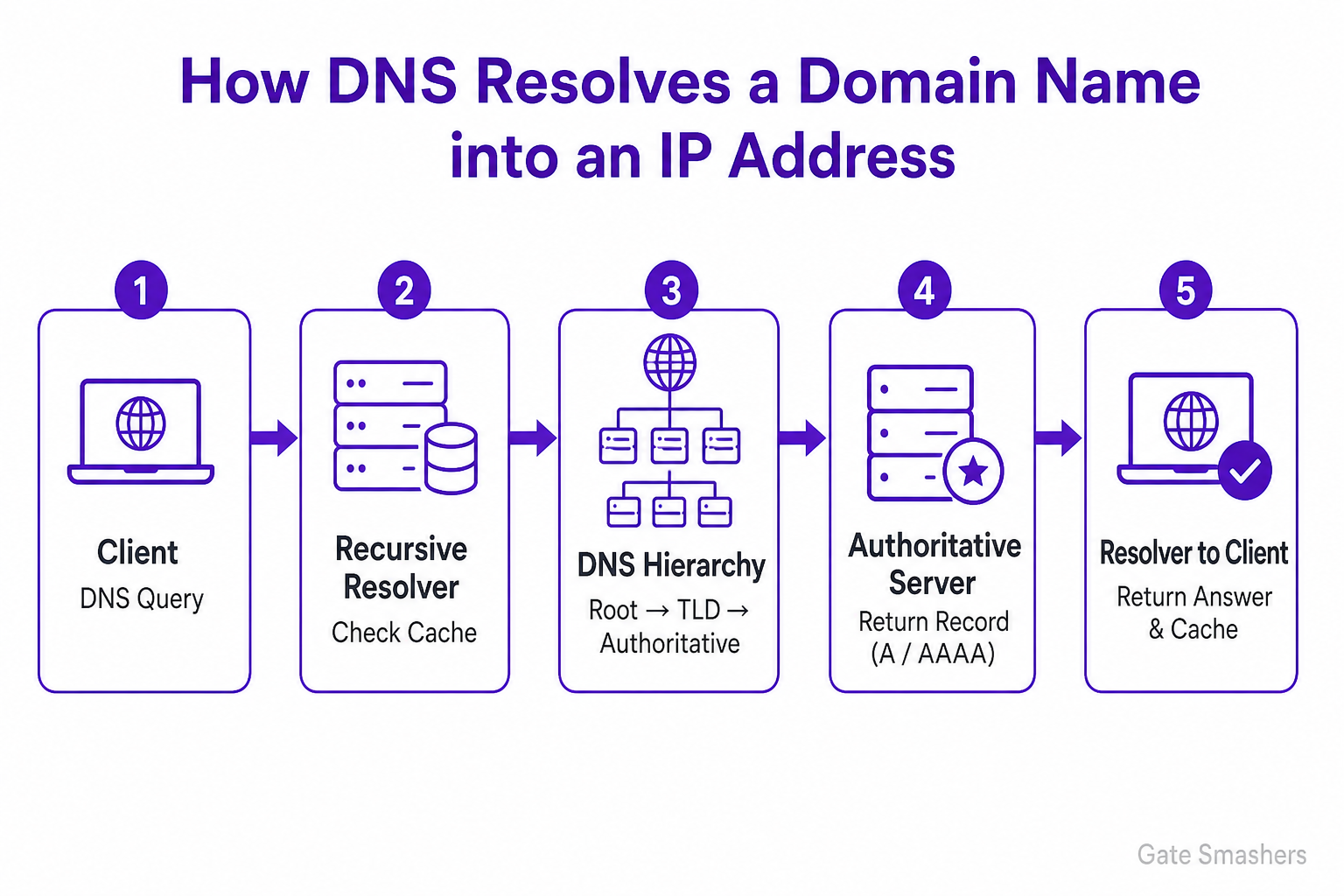
DNS resolves a domain name by asking a recursive resolver to find the relevant DNS record, usually an A record for IPv4 or an AAAA record for IPv6. The resolver first checks its cache. On a cache miss, it follows the DNS delegation hierarchy—root servers, top-level-domain servers, and the domain’s authoritative servers—then returns the result to the client and caches it according to its TTL.
Client query and caching
When an application needs an address for a name such as example.com, it sends a DNS query to a configured recursive resolver. The application, operating system, or resolver may already have a usable cached answer, in which case no external DNS lookup is needed.
The recursive resolver is commonly supplied by an organization, ISP, router, or public DNS provider. It performs the lookup on the client's behalf when it does not have a cached answer.
DNS hierarchy and delegation
For an uncached name, the resolver typically begins by querying a root DNS server. The root server does not usually provide the final address; it returns a referral to the servers responsible for the relevant top-level domain, such as .com.
The resolver then queries a top-level-domain server, which returns a referral to the authoritative name servers for the domain. Finally, the resolver queries an authoritative server, which provides the requested DNS record or another applicable response.
- Root servers: Refer the resolver to the appropriate top-level-domain servers.
- TLD servers: Refer the resolver to the domain's authoritative name servers.
- Authoritative servers: Provide the domain's DNS data, such as A, AAAA, or CNAME records.
Aliases, responses, and caching
An A record contains an IPv4 address, while an AAAA record contains an IPv6 address. If the queried name has a CNAME record, the resolver follows the alias to its target name and resolves that target as needed.
The resolver returns the resulting DNS response to the client. It normally caches cacheable data for the TTL specified in the DNS records, allowing later queries to be answered more quickly until the cached entry expires.
Transport
Traditional DNS queries commonly use UDP port 53. TCP port 53 is used when needed, including for zone transfers and for responses that cannot be handled over UDP.
21How does HTTPS secure communication between a browser and a server?
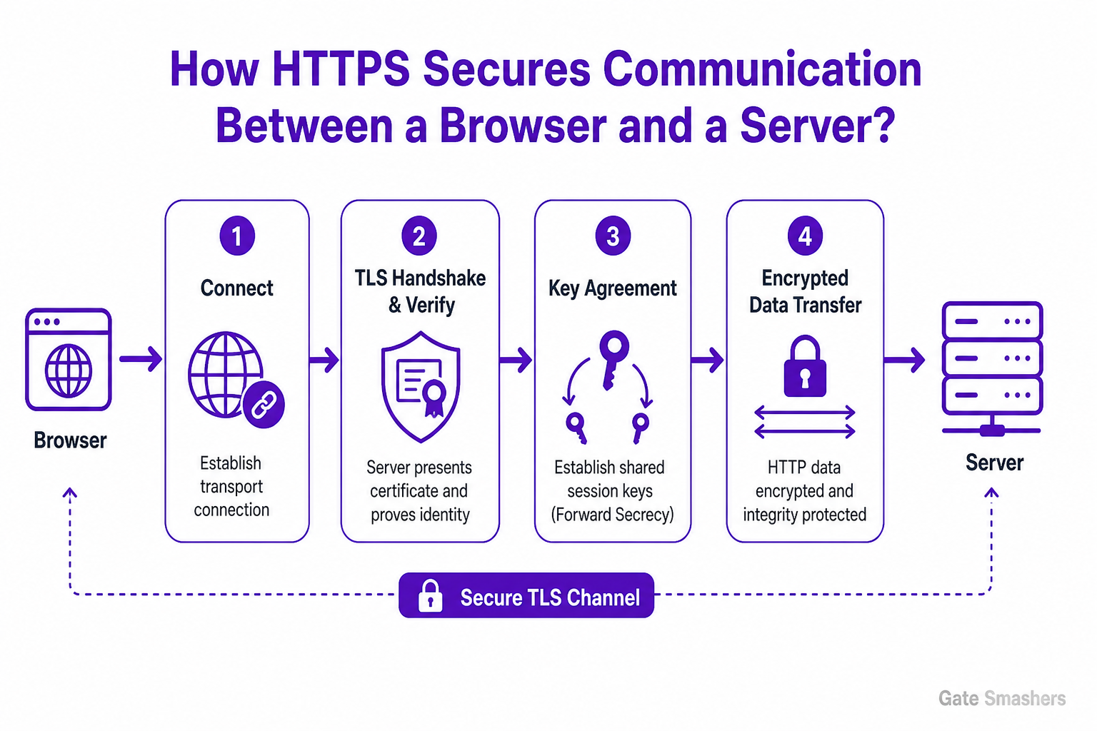
HTTPS secures web communication by running HTTP over TLS. TLS authenticates the server, establishes shared session keys, encrypts HTTP data, and detects tampering in transit. The browser validates the server’s certificate during the TLS handshake, then both sides use derived symmetric keys to protect requests and responses.
HTTPS and TLS
HTTPS is HTTP carried over Transport Layer Security (TLS). TLS creates a protected communication channel between the browser and the server before normal HTTP messages are exchanged. It provides confidentiality, integrity, and authentication of the server in the usual HTTPS deployment.
Connection setup and certificate validation
The browser first establishes the underlying transport connection. This is usually TCP for HTTP/1.1 and HTTP/2; HTTP/3 uses QUIC, which runs over UDP and incorporates TLS handshake functionality.
During the TLS handshake, the server presents a certificate containing its public key and identity information. The browser checks that the certificate chains to a trusted certificate authority, is valid for the requested hostname, and is within its validity period. The server also proves possession of the corresponding private key as part of the handshake.
Key agreement and protected data transfer
The browser and server negotiate TLS parameters and perform key agreement, commonly using ephemeral key exchange. They derive shared session keys without sending those final keys directly over the network. Ephemeral key exchange can provide forward secrecy, meaning that compromise of a server’s long-term private key does not normally reveal past sessions.
After the handshake, HTTP requests and responses are protected using symmetric cryptography. TLS encryption prevents network observers from reading the application data, while authenticated encryption or equivalent integrity mechanisms allow the recipient to detect altered, injected, or forged records.
Security boundaries
HTTPS protects data while it travels between the browser and the authenticated server endpoint. It does not prove that a website operator is honest, that the site is free from vulnerabilities, or that data remains protected after the server receives it. Client authentication is possible with TLS certificates, but it is not normally used for standard web browsing.
22What happens in the network after a user enters a URL in a browser?
After a user enters a URL, the browser parses it, checks available caches, resolves the hostname through DNS if necessary, connects to the selected server, secures the connection for HTTPS, sends an HTTP request, receives a response, fetches referenced resources, and renders the page. Some steps may be skipped, reused, or performed concurrently because of caching, connection reuse, HTTP/2, or HTTP/3.
1. URL parsing and local checks
The browser separates the URL into components such as the scheme, hostname, port if specified, path, query, and fragment. The fragment is normally handled locally by the browser and is not sent in the HTTP request.
Before making network requests, the browser may use cached HTTP responses, cached DNS records, service-worker-controlled responses, or an existing reusable connection. Cache rules and browser policies determine whether a cached response can be used or must be revalidated.
2. DNS resolution and delivery across the network
If the hostname is not already resolved, the browser or operating system obtains one or more IP addresses through DNS. The selected address may belong to the origin server, a content delivery network, or another intermediary.
The host consults its routing table to choose a next hop, commonly the local default gateway for off-network destinations. On a local Ethernet or Wi-Fi network, it resolves the link-layer address of that next hop when needed. Routers then forward IP packets toward the destination; network address translation may occur at a network boundary.
- DNS: Maps the hostname to one or more IP addresses.
- Routing: Determines the next hop used to send packets toward the selected address.
- NAT: May translate private and public addresses, but is not required for every connection.
3. Transport, TLS, and the HTTP request
For HTTP/1.1 or HTTP/2, the browser commonly uses TCP and establishes a connection before exchanging HTTP data. HTTP/3 uses QUIC, which runs over UDP and incorporates transport security. A previously established connection may be reused when permitted.
For an HTTPS URL, TLS authenticates the server using its certificate and negotiates encryption keys. The browser then sends an HTTP request containing a method, target path, headers, cookies when applicable, and an optional request body.
- TCP: Commonly carries HTTP/1.1 and HTTP/2.
- QUIC: Carries HTTP/3 over UDP.
- TLS: Protects HTTPS traffic and authenticates the server, subject to certificate validation.
4. Response processing and rendering
The request may be handled by a CDN, reverse proxy, load balancer, application server, cache, or database, depending on the service architecture. The responding component returns an HTTP status code, headers, and a response body, which may be HTML or another type of content.
When HTML is received, the browser parses it and discovers referenced resources such as stylesheets, scripts, images, and fonts. It requests those resources as needed, applies CSS, executes JavaScript where required, calculates layout, paints the result, and displays the page. Resource loading and rendering can overlap, and JavaScript or later network responses can update the page after the initial display.
23A computer is connected to Wi-Fi but cannot open any website. How would you troubleshoot the problem step by step?
I would troubleshoot from the device outward and use each result to isolate the failing layer. First confirm that the computer is associated with the intended Wi-Fi network and determine whether other devices on that network can access websites. Then verify that the computer has a valid IP address, default gateway, and DNS configuration. Test reachability to the local gateway, then test access to a known public IP address, and finally test DNS name resolution. If network and DNS tests are successful, investigate web-specific causes such as a captive portal, proxy, VPN, firewall or endpoint-security policy, and browser settings. If several devices are affected, focus on the access point, router/firewall, WAN connection, DNS service, or ISP rather than the individual computer.
1. Confirm the scope and Wi-Fi association
Check that the computer is connected to the correct SSID, has an adequate signal, and is not in airplane mode or otherwise disconnected. Also check whether another device on the same Wi-Fi can browse normally.
This immediately distinguishes a device-specific problem from a network-wide problem. A Wi-Fi connection only confirms association with the access point; it does not confirm usable IP connectivity or Internet access.
- Only one device fails: Prioritize that computer's network configuration, security controls, and applications.
- Multiple devices fail: Prioritize the access point, router/firewall, WAN connection, DNS service, or ISP.
2. Validate IP configuration and local connectivity
Inspect the assigned IP address, subnet mask or prefix, default gateway, and DNS servers. The address and gateway should be appropriate for the local network. On IPv4, a 169.254.x.x address commonly indicates that the device did not obtain an address through DHCP.
Test the local TCP/IP stack if needed, then test the default gateway. Failure to reach the gateway suggests a local-network issue, such as incorrect addressing, failed DHCP, Wi-Fi isolation, an access-point or router issue, or local filtering. A ping result alone is not conclusive because some devices block ICMP, so use other available connection tests where appropriate.
- No valid address or gateway: Reconnect to Wi-Fi, renew the address lease where supported, and check DHCP or static network settings.
- Gateway unreachable: Investigate the wireless link, local addressing, access-point configuration, and router availability.
3. Separate Internet routing from DNS
If the gateway is reachable, test connectivity to a known public IP address. Successful access to a public IP indicates that basic routing beyond the local network is likely working. Failure points toward the router, firewall, WAN link, or upstream provider.
Next, perform a DNS lookup for a domain name and verify that the configured DNS servers are reachable and returning results. If public-IP connectivity works but names do not resolve, DNS configuration or the DNS service is the likely fault domain. Use an alternative approved DNS resolver only if organizational policy permits it.
- Public IP works, names fail: Check DNS server settings, DNS reachability, and DNS filtering or outages.
- Public IP fails: Check the router or firewall, WAN status, upstream routing, and ISP service.
4. Check web-specific and application-specific causes
If IP connectivity and DNS resolution work but websites still do not open, check for a captive portal that requires sign-in, an incorrect proxy configuration, VPN behavior, firewall or endpoint-security restrictions, and browser extensions or browser security settings.
Try another browser or another Internet-enabled application. If only one browser fails, reset or correct that browser's settings. If all browsers and applications fail while network tests succeed, focus on system-wide proxy, VPN, security, or policy controls.
- Captive portal: Complete the required sign-in or accept the network terms.
- Proxy or VPN: Verify that the configured service is reachable and required settings are correct.
- Security controls: Review firewall, endpoint-security, and organizational web-filtering policies for blocks.
24How would you respond to a suspected network security breach?
I would follow the organization’s incident-response plan: validate and triage the alert, contain the threat, preserve evidence and determine scope, eradicate the cause, recover services safely, monitor for recurrence, meet communication obligations, and perform a post-incident review.
Validate and contain the incident
I would first confirm that the alert represents a genuine security incident, assess its severity, and identify the affected systems, accounts, network segments, and indicators of compromise. I would activate the incident-response process so technical, management, legal, and communications actions are coordinated.
Containment should limit further access, lateral movement, and damage while minimizing disruption and avoiding unnecessary loss of evidence.
- Validate and triage: Correlate alerts, logs, endpoint findings, and network activity to confirm the incident and establish an initial priority.
- Contain: Isolate compromised hosts or segments, block known malicious traffic, and disable or restrict compromised accounts or access paths as appropriate.
Preserve evidence and determine scope
I would preserve relevant evidence according to organizational and legal procedures. Where feasible, I would collect volatile information before actions such as rebooting or rebuilding systems, because that information may be lost.
In parallel, I would investigate the entry point, attacker activity, affected assets, privilege changes, persistence, lateral movement, and possible data access or exfiltration. This establishes the scope of remediation and supports any required reporting.
- Preserve evidence: Retain relevant logs, alerts, timestamps, packet captures, volatile data, and forensic images using approved handling procedures.
- Determine scope: Identify the initial access path, affected systems and accounts, attacker persistence, lateral movement, and potential impact on data or services.
Eradicate, recover, and monitor
After understanding the incident sufficiently, I would remove malicious artifacts and persistence mechanisms and correct the weakness that enabled the breach. Remediation may include patching vulnerabilities, correcting insecure configurations, removing unauthorized access, and rotating compromised credentials or secrets.
I would restore systems from known-good sources or rebuild them as needed, verify security controls and configurations, and return services to production in a controlled manner. Enhanced monitoring is needed after recovery to detect missed activity or recurrence.
- Eradicate: Remove malware and persistence, revoke unauthorized access, patch exploited weaknesses, and remediate unsafe configurations.
- Recover safely: Restore or rebuild affected systems, validate their integrity and configuration, and reconnect them in a controlled sequence.
- Monitor: Closely review authentication activity, endpoint telemetry, network traffic, logs, and relevant indicators of compromise.
Communicate and improve the response
I would follow internal escalation procedures and engage the appropriate stakeholders. External notifications, regulatory reporting, customer communication, and law-enforcement involvement must be handled according to applicable obligations and organizational policy.
After the incident is contained and recovered, I would conduct a post-incident review to document the timeline, impact, decisions, root cause, and improvements needed in controls and response processes.
- Communicate and report: Provide accurate, need-to-know updates and meet applicable internal and external notification requirements.
- Lessons learned: Use the review to improve detection, segmentation, access controls, backups, patching, and incident-response procedures.
25Explain how you would protect an organization against DDoS attacks.
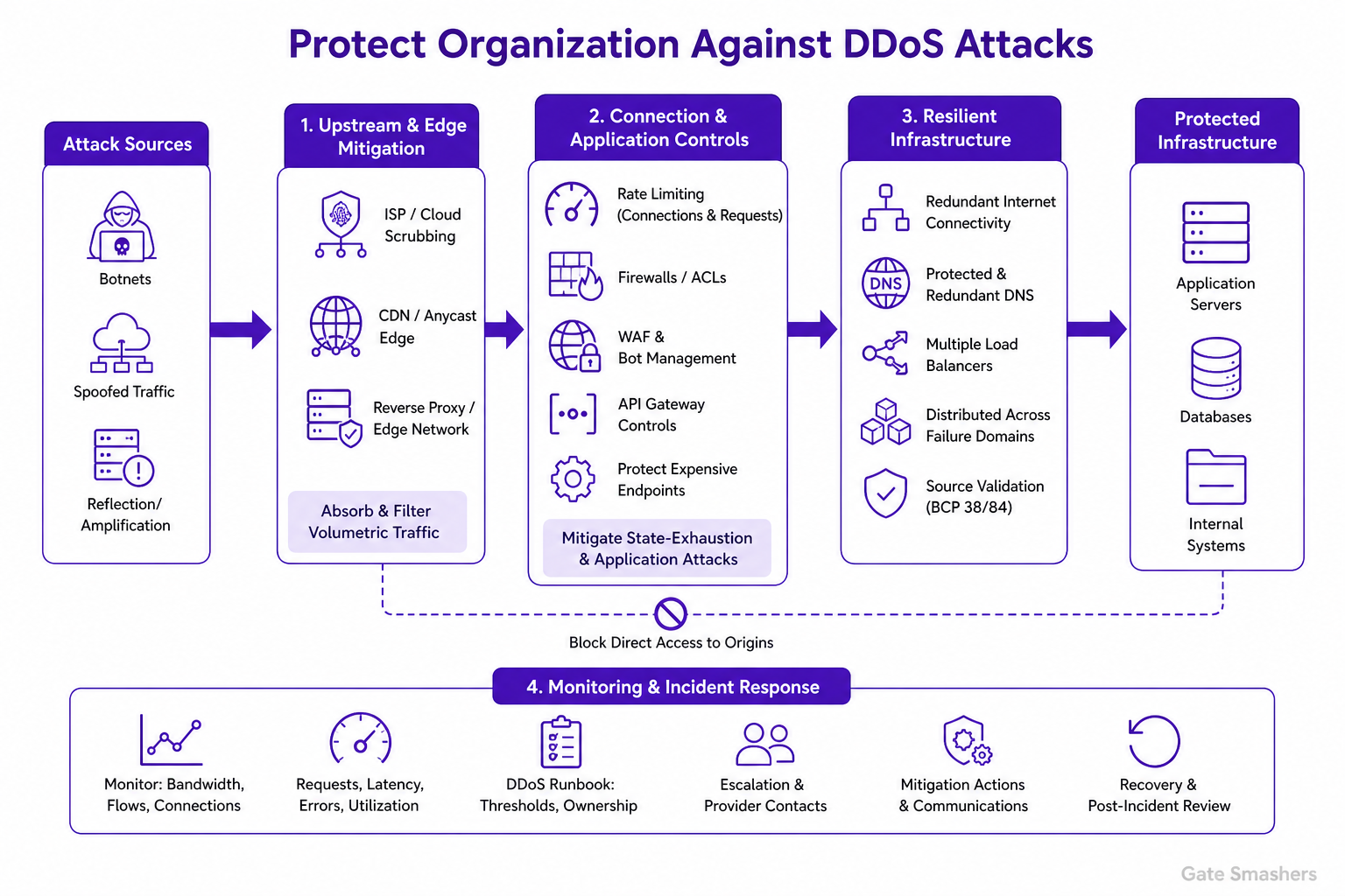
I would use a layered DDoS-defense strategy that combines upstream mitigation, distributed edge capacity, application controls, resilient infrastructure, and an exercised incident-response plan. The key principle is to stop traffic as far from the origin as possible: if a volumetric attack saturates the organization’s Internet link, an on-premises firewall cannot restore that lost bandwidth. Large attacks therefore require ISP, cloud, or dedicated scrubbing protection upstream of the organization. At the network and edge layers, I would use a DDoS-protection provider, CDN, reverse proxy, or Anycast-based edge where appropriate. These services absorb and filter high-volume traffic before forwarding legitimate requests to protected origins. I would also restrict direct access to origin systems so that attackers cannot bypass the edge. For state-exhaustion and application-layer attacks, I would apply connection and request rate limits at suitable points such as load balancers, API gateways, firewalls, and applications. A WAF and bot-management controls can identify malformed requests, abusive automation, suspicious request patterns, and attacks against expensive application endpoints. Limits should be designed carefully so legitimate traffic is not unnecessarily blocked. I would build resilience through redundant Internet connectivity where justified, protected and redundant authoritative DNS, multiple load balancers, and capacity distributed across failure domains. Network ACLs and source-address validation, where under organizational or provider control, can reduce unwanted and spoofed traffic. Finally, I would continuously monitor bandwidth, flow data, connection counts, request rates, latency, error rates, and resource utilization. A tested DDoS runbook should define detection thresholds, ownership, escalation paths, provider contacts, mitigation actions, communications, and recovery steps. Regular testing ensures the technical controls and operational response work together during an actual attack.
Defense strategy and attack layers
DDoS attacks may exhaust Internet bandwidth, network-device or server connection state, or application resources. Effective protection is therefore layered rather than dependent on a single firewall or appliance.
Volumetric attacks must be mitigated before they saturate the organization’s Internet connection. Once the link is full, local systems may remain reachable internally but external users cannot reach them.
Upstream and edge mitigation
Use ISP, cloud, or dedicated traffic-scrubbing services to detect and filter large attack traffic upstream. A CDN, reverse proxy, or distributed edge network can absorb traffic across a larger footprint and forward only permitted traffic toward the origin.
Protect origin infrastructure from direct exposure. Public services should be reachable through the intended protected entry points, while origin access is limited to necessary sources and paths.
- Upstream filtering: Removes volumetric attack traffic before it consumes the organization’s access bandwidth.
- Distributed edge: Distributes public traffic across multiple edge locations and reduces dependence on a single origin-facing connection or site.
Connection and application-layer controls
Apply rate limits and connection controls at the layers that can enforce them effectively, such as load balancers, API gateways, firewalls, and application servers. Controls should protect scarce resources, especially endpoints that trigger expensive processing.
Use application-aware defenses for HTTP(S) attacks. A WAF and bot-management capabilities can enforce request validation and identify abusive automation or suspicious behavior. Policies require tuning to avoid blocking legitimate users during traffic spikes.
- Rate and connection limits: Constrain unusually high request rates, concurrent connections, and repeated access to sensitive endpoints.
- WAF and bot controls: Help mitigate malicious HTTP requests and automated abuse using application-aware rules and signals.
Resilience, monitoring, and response
Remove avoidable single points of failure through suitable redundancy in connectivity, load balancing, service capacity, and authoritative DNS. Use network filtering and source-address validation where the organization or its providers control those networks.
Monitor network traffic and service health continuously so attacks can be identified quickly. Maintain and regularly test a DDoS runbook that coordinates technical mitigation with provider escalation, internal responsibilities, communications, and recovery.
- Monitor: Track bandwidth, traffic flows, connection counts, request rates, latency, error rates, and resource utilization.
- Prepare: Document escalation contacts, thresholds, mitigation procedures, decision ownership, and recovery actions.